East Coast Part Supplier and Warehouse Association Moderated Interchange Newsgroup > North Carolina
> Machinery
> Medical and Dental
> LA4000 4240 40 channel electronic logic analyzer link
LA4000 4240 40 channel electronic logic analyzer link
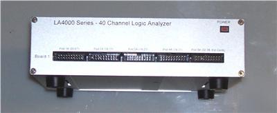
LA4000 4240 40 CHANNEL LOGIC ANALYZER LINK INSTRUMENT
We deal in items we believe others will enjoy and want to purchase.
We welcome any comments, questions, or concerns.
WE ARE TARGETING A GLOBAL MARKET PLACE.
WHO NEEDS TRANSLATION SERVICE, PLEASE CONTACT US.
Thanks in advance for your patronage.
Be sure to add me to your favorites list!
NOW FOR YOUR VIEWING PLEASURE…
MANUFACTURED FROM FAIRFIELD, NEW JESREY (NJ).
OPERATIONS MANUAL IS AVAILABLE ON LINE PDF FORMAT.
Variable (-6.52V to +6.12V), each pair of pods can be set to different voltage settings
Inputs are clamped through a 200KΩ resistor. ± 150V Cont., 250V Trans.
200MSa, 100MSa, 50MSa, 20MSa, 10MSa, 5MSa, 2MSa, 1MSa, 500KSa, 200KSa, 100KSa, 50KSa, 20KSa, 10KSa, 5KSa, 2KSa, 1KSa, 500Sa, 200Sa, 100Sa, 50Sa, 20Sa, 10Sa, 5Sa, 2Sa and 1Sa
500MSa, 250MSa, 100MSa, 50MSa, 20MSa, 10MSa, 5MSa, 2MSa, 1MSa, 500KSa, 200KSa, 100KSa, 50KSa, 20KSa, 10KSa, 5KSa, 2KSa, 1KSa, 500Sa, 200Sa, 100Sa, 50Sa, 20Sa, 10Sa, 5Sa, 2Sa and 1Sa
8 external clocks can be combined to form a versatile sampling clock
8 external clocks can be used as qualify lines
Channel to channel, < 2ns typical
EPP, bi-directional, 8bit, 4bit, or normal parallel port
Win XP, Win 2K, Win NT, Win 98, Win ME, Win 95
Win XP, Win 2K, Win 98, Win ME
(40 Ch @1Sa/s to 100MSa/s, 32KB)
0,1 and DON'T CARE for all channels
Duration Timer: <= n, or >= n clocks; where n is 1 to 255
Trigger on the condition becoming true or becoming false
Trigger position can be set anywhere in the capture buffer
If trigger conditions are met, acquire a buffer worth of data
If trigger conditions are met, acquire a buffer worth of data, then restart
If trigger conditions are not met within a set time, acquire a buffer worth of data, then restart
Any of the logic analyzer inputs can be used as trigger in.
BNC connector on rear of logic analyzer
The LA-4000 series of parallel port and USB logic analyzers offer all of the features and performance you have come to expect: high speed clock rates, deep data buffers, sophisticated triggering, easy data management and large color displays.
The PC Based instruments are controlled with easy to use Windows software. This allows for more organized data display (with color coded data and increased screen size), intuitive user interface, and data management (file saving, loading, sharing and exporting to other software and reports).
Our logic analyzers connect to your PC's parallel port or USB port and take advantage of your large color screen, disk drives and printers. They are compact and don't have screens, drives, knobs or buttons - saving you money and space.
The LA-4000 PC Based logic analyzer series can be configured to be a pattern generator with the purchase of optional pattern generator pods.
The LA-4000 series logic analyzers are available in USB and parallel port versions that connect to your laptop or desktop Windows computer.
* Allows connection between an LA-4000 series logic analyzer and the USB port of your laptop or desktop computer
* Universal power supply (90-240V, 47-63Hz)
* Compatible with Win XP, Win 2000, Win 99 and Win Me software only
* Allows connection between a LA-4000 series logic analyzer and the parallel port of your laptop or desktop computer
* Universal power supply (90-240V, 47-63Hz)
* Supports EPP, 4 bit and 8 bit parallel communication modes
* Compatible with Win95, Win 98, Win ME, Win NT, Win 2K, and Win XP software only
A logic analyzer displays signals in a digital circuit that are too fast to be observed by a human being and presents it to a user so that the user can more easily check correct operation of the digital system. Logic analyzers are typically used for capturing data in systems that have too many channels to be examined with an oscilloscope. SW running on the logic analyzer can convert the captured data into timing diagrams, protocol decodes, state machine traces, assembly, or correlate assembly with source-level software.
Current analyzers are either mainframes, which consist of a chassis containing the display, controls, control computer, and multiple slots into which the actual data capturing hardware is installed, or standalone units which integrate everything into a single package, with options installed at the factory. Recent mainframe models include the Agilent 16900 and Tek TLA7000, and recent standalone models include the Agilent 16800-series and Tek TLA5000.
Agilent and Tektronix make up over 95% of the industry's revenue.
A logic analyzer can trigger on a complicated sequence of digital events, and then capture a large amount of digital data from the system under test (SUT). The best logic analyzers behave like software debuggers by showing the flow of the computer program and decoding protocols to show messages and violations.
When logic analyzers first came into use, it was common to attach several hundred "clips" to a digital system. Later, specialized connectors came into use. The evolution of logic analyzer probes has led to a common footprint that multiple vendors support, which provides added freedom to end users. Since 2004, connectorless technology, known as Soft Touch, has become popular. These probes provide a durable, reliable mechanical and electrical connection between the probe and the circuit board with less than 0.7 pF loading per signal.
After the mode is chosen, a trigger condition must be set. A trigger condition can range from simple (such as triggering on a rising or falling edge of a single signal), to the very complex (such as configuring the analyzer to decode the higher levels of the TCP/IP stack and triggering on a certain HTTP packet).
At this point, the user sets the analyzer to "run" mode, either triggering once, or repeatedly triggering.
Once the data is captured, it can be displayed several ways, from the simple (showing waveforms or state listings) to the complex (showing decoded Ethernet protocol traffic). The analyzer can also operate in a "compare" mode, where it compares each captured data set to a previously recorded data set, and stopping triggering when this data set is either matched or not. This is useful for long-term empirical testing. Recent analyzers can even be set to email a copy of the test data to the engineer on a successful trigger.
Many digital designs, including those of ICs, are simulated to detect defects before the unit is constructed. The simulation usually provides logic analysis displays. Often, complex discrete logic is verified by simulating inputs and testing outputs using boundary scan. Logic analyzers can uncover hardware defects that are not found in simulation. These problems are typically too difficult to model in simulation, or too time consuming to simulate and often cross multiple clock domains.
FPGAs have become a common measurement point for logic analyzers.