East Coast Part Supplier and Warehouse Association Moderated Interchange Newsgroup > Pensylvania
> Production
> Welding and Gluing
> Mini-rtc (I2C real time clock) basic stamp, pic, atmel
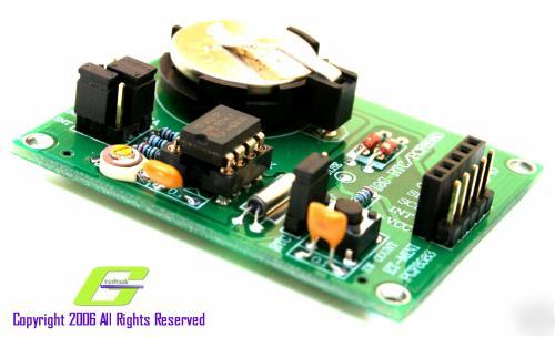
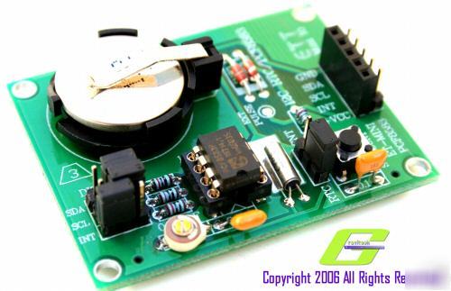
Mini-rtc (I2C real time clock) basic stamp, pic, atmel
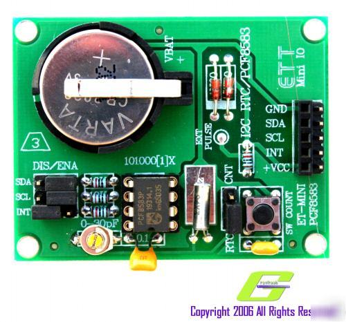
There are two modes of operation RTC mode and counter mode. When using RTC mode, there is a variable capacitor for frequency crystal adjustment. This makes crystal create correct frequency result in accurate time base. There is a on-board battery backup when there is no power apply to the board. This enable RTC to run continuously even without power supply. When using counter mode (CNT), user can input pulse signal from external generated source via a header pin. Moreover, there is an on-board push button switch so user can generate the pulse to test or experiment with this feature.
Please take a look at PCF8583 datasheet for more information.
· I2C bus interface operating supply voltage: 2.5V to 6V
· Clock function with four year calendar
· Thermal shutdown and current limit protection
· On-board variable capacitor for frequency adjustment
· Jumpers setting configuration
· Four mounting holes on each corner
· Male and female output headers
For more information please see: MR-MINI-RTC User Manual
“This is sold fully assembled and testedâ€
For more exciting products please visit WWW.MICRORESEARCH.US